�㽭���ܴ�¯ҵ����˾
�֡����� 13705828806
�硡����0572-6871999 6087213 6870511
�����棺0572-6087105
E-mail��1390003299@qq.com
�� ַ���㽭ʡ�������ֳǹ�ҵ�����˱�·6�ţ��ֳǸ���·����20����ࣩ
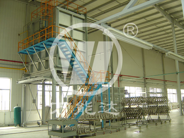
��Ӧ����¯�����ȴװ�õ����Ҫ��
Ϊ�˱�֤��Ӧ����¯�����ȴ������ȴ��������ȴЧ��������ƴ����ȴ ��ʱҪע�����м��㡣
1��ȷ������ȴ������ȴ������ȴ�������ǵ�λʱ������ ȴ�������ղ��ŷŵ�������MJ・h������ȴ����Ҫ���ڸֲĴ�� �����ų������ܡ���ȴ���ʴ��ߵ�������ֲ��ͷų�������֮���� ��С����ʾ�����ȴ������ȴ������
2�������ȴ����Ӧ�����㹻��ѹǿ��ȴ���ʵ�ѹǿ���ṩ ����������Һ�������ܵĻ�����Һ�������㹻�Ķ��ܲ��ܳ����� Ĥ�����ָߵ���ȴ�ٶȡ���ȴ���ʵ�ѹǿ����ֲijߴ������� ���ߡ�ֱ����100mrn���µĹܲĺ�ֱ����60mm���µİ��ģ������ȴʱʹ�ô����ʵ�ѹǿΪ0.2〜0. 5MPa���������ϳߴ�� �ܲĺͰ��ģ������ʵ�ѹǿ���ʵ������0. 3〜0. 6MPa����� ���Ĵ�����ѹǿҪ�������ʵ�ʽ��е������������ݽ����ο���
3����ˮ�װ�ijߴ���ˮ�װ����ƺ������ֱ�ӹ�ϵ����ȴ������ȴЧ�����װ������Ҫ���պ���������Ҫ�㡣
3.1��ˮ�ܵĺ�����Ҫ������ˮ��������������ܱ�����ˮע���㹻��ѹǿ��ͨ����ˮ�ܵ�����ȳ�ˮ���������10% ���ҡ�
3.2��ˮ��ֱ���Ϳ�Ҫ������ˮ��ֱ����С���ײ�����������ʴ��Ӱ����ȴ�ľ����ԡ���������Ȼ������ˮ ע�ij���㣬Ҳ�ή����ȴ�ľ����ԡ����ʵĿ��Ϳ״�� �ֲĵijߴ����ѡ����ͨ������¿�Ӧ������2〜3mm,8〜10mm,����������ʵ��Ŵ�
4�����ˮ�������ŵ�Ҫ�������ŵ��Ƿ���ȣ�һ����ƽ����ķֲ�����һ���滹ȡ��������������ر��ǿ����ȡ����ֲ���תǰ��ʱ�������ֲ����ŵ㲻������ɵ�ȱ�㡣���� ʽ��ȴ��������ˮ����ȴ��������ˮ�ڵĽǶ�Ӧ����һ�²��ܲ��� ǿ������ת������ǿ����ȴЧ����
5����ֹ�����ʺ�ˮ����������ȸ�Ӧ��һ�������ʽ� ����ȸ�Ӧ���ڣ�����Ӱ��ֲ��¶ȣ�����ʱ��ʹ��Ӧ���Ѽ��· ���˸�Ӧ��Ȧ����ˣ������ֹ�����ʺ�ˮ����������ȸ�Ӧ�� �ڡ������ʩ���¡�
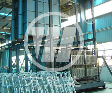
6������Ӧ����¯�����ȴ�����Ӧ��֮���赲ˮ������ˮ�������ͻ��˲����Ƴɣ����¸ֲĴ�Ԥ������ͨ����������ȴ����
6.1��������ȴ������ˮ��������������ȴ��.ʹ��ȴ ˮֱй���²�ˮ�䣬������ȴ���ڲ���ˮ��
6.2�����ȴ�����ϲ�����οװ壬���Է�ֹ��ȴ���������
Key Points in Design of Quenching and Cooling Device of Induction Heating Furnace
In order to ensure the cooling capacity and cooling effect of the quenching cooler of the induction heating furnace, the following points should be paid attention to when designing the quenching cooler.
1. Accurately calculate the cooling capacity of the cooler. The cooling capacity is the heat energy absorbed and discharged by the cooling medium per unit time (MJ��h). The cooling capacity is greater than the heat energy discharged from the quenching and cooling of the steel. The ratio of the heat energy taken away by the cooling medium to the heat energy released by the steel indicates the cooling capacity of the quenching cooler.
2. The quenching and cooling medium should have sufficient pressure. The pressure of the cooling medium is the basis for the flow energy of the sprayed liquid column provided to the medium. The liquid column flow has enough kinetic energy to break through the gas film and maintain a high cooling rate. The pressure of the cooling medium increases as the size of the quenched steel increases. 3 For pipes with a diameter of less than 100mrn and bars with a diameter of 60mm or less, the pressure of the quenching medium used during quenching and cooling is 0.2~0. 5MPa; for pipes and bars larger than the above size, the pressure of the quenching medium can be appropriately increased to 0.3 ~0. 6MPa. The quenching medium pressure to be used should be adjusted according to the actual production. The above data is for reference only.
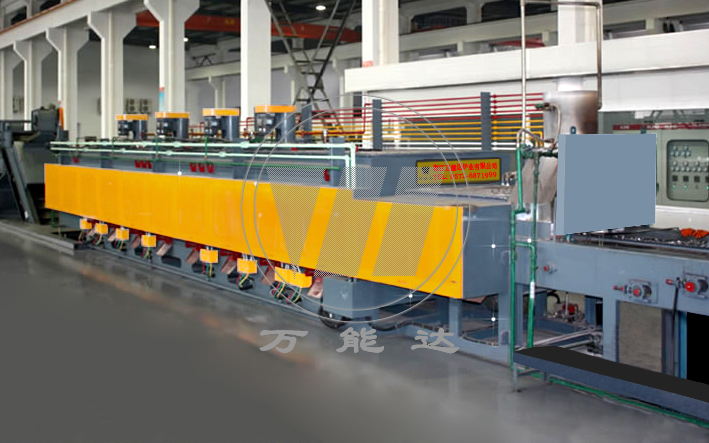
3. The size of the water spray orifice. Whether the design of the water spray orifice is reasonable or not is directly related to the cooling effect of the cooler. The following two points must be grasped in the design of the orifice plate.
3.1 The cross-sectional area of the water inlet pipe must be larger than the total area of the spray hole in order to maintain sufficient pressure for the spray jet. Usually the area of the inlet pipe is about 10% larger than the total area of the outlet hole.
3.2 The diameter and pitch of the spray holes should be appropriate. If the diameter of the spray holes is too small, it is easy to cause blockage or rust, which affects the uniformity of cooling. If the hole diameter is too large, the hole distance will inevitably increase the impact point of less water injection, and will also reduce the uniformity of cooling. The appropriate hole diameter and the size of the hole quenched steel are selected. Under normal circumstances, the aperture should be controlled at 2~3mm, 8~10mm, special circumstances can be appropriately enlarged.
4. The spray point of the quenching water column should be uniform. Whether the spray point is uniform, on the one hand, the average spray hole distribution, on the other hand, also depends on the quality of the drilled hole, especially the depth of the hole. When the steel rotates forward, it can make up for the shortcomings caused by uneven spraying points. In the vortex cooler and the tangential water column cooling method, the angle of the water nozzles should be the same to generate a strong swirling vortex and enhance the cooling effect.
5. Prevent the quenching medium and water vapor from entering the heating inductor. Once the quenching medium enters the heating inductor, the lighter will affect the temperature of the steel, and the severer will cause a short circuit between the inductors and damage the induction coil. Therefore, it is necessary to prevent the quenching medium and water vapor from entering the heating inductor. The specific measures are as follows.
6. A water-retaining curtain is set between the quenching cooler of the induction heating furnace and the inductor. The water-retaining curtain is made of fire-resistant chemical fiber cloth strips, and the high-temperature steel enters the quenching cooler through the reserved holes.
6.1 Expand the area of the drainage hole of the quenching cooler or design a bottomless cooler. Let the cooling water drain directly into the lower water tank to keep no water in the cooler.
6.2 A tapered orifice plate is used on the feed side of the quenching cooler to prevent the cooling medium from overflowing.


�� ����0572-6871999 �� ����13936361130 13705828806